|
Restoring |
 |
|
Restoring |
|
|
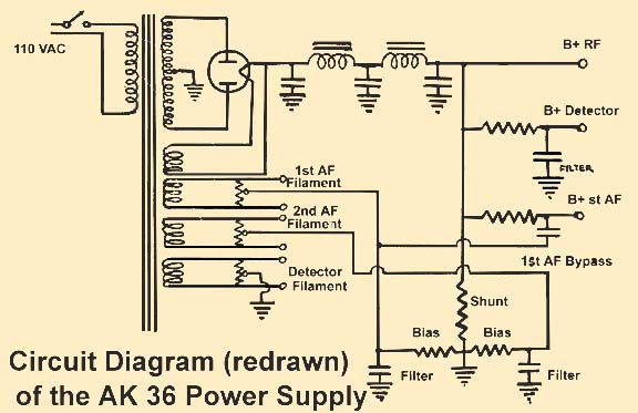
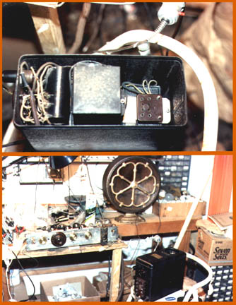
The early AK 36 model "Y" power supply differs from the RB battery eliminator by having center tapped windings for the A.C. powered tubes. There is a plug on the side for the on-off switch located on the radio. There is a hum balance control next to the plug. The terminals for the high voltage are exposed on a card just below. This was dangerous and was discontinued on the revision of this set. This page is divided into 5 parts: Disassembly, Transformer, Filters, and Restoration-Reassembly. You can click on any of the small pictures to view the full size picture. The diagram (below) had to be redrawn because the original was too difficult to read. |
|
|
|
Disassembly - (Click to view large pix)
|
|
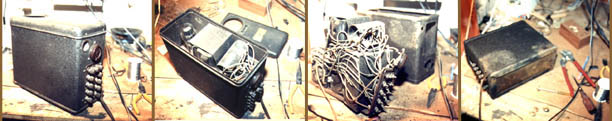
The power supply disassembly found several bad problems. First the metal cabinet had scratches, rust, and even some missing paint. The filters were bad as well as the transformer. The rust was removed while the parts were cleaned. Then a mixture of black and burnt umber tube acrylic paint was mixed to match the original color (used sunlight). The scratches were touched up and areas where paint was missing was redone by using a large very soft brush that was almost dry and dobbing the surface to match the original crackle finish. after the paint was matched perfectly (it took several tries) the entire case was sprayed with two coats of semi-gloss acrylic lacquer which fused all the paint together seamlessly. The transformer, power cable and the filters will be covered in the next pictures followed by reassembly and testing. |
|
Transformer - (Click to view large pix) |
|
|
|
|
|
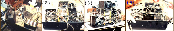
Figure ( 1 ) shows the alignment of the transformer in the can after some tar was removed. Fig. ( 2 ) shows heating the can to melt the potting tar (I made a big mess I had to clean up). Fig. ( 3 ) shows the empty can, the can of tar, and the transformer (which was open and had to be replaced). Fig. ( 4 ) shows how I dumped the transformer after I dumped the tar. |
|
| The old windings
were generating 2.3 volts at no load but only .8 volts at the 26 tubes.
This meant that there was a 1.5 volt voltage drop under load at the 26
tubes. To have 1.5 volts at the 26 tubes about 3 volts would have to be
generated at the transformer. A test winding of five turns on the
transformer produced .8 volts under no load: Therefore:
3 volts - desired
voltage X
turns
X = 19 turns 19 turns on the transformer actually produced 1.6 volts at the 26 tubes but this was within the tube's operating parameters and allows for an increase in resistance in the cord due to heat. |
|
Filter Capacitors - (Click to view large pix ) |
|
|
|
|
|
The filters were replaced without removing the old filters from the can. Enough tar was removed to place six new two mfd. tubular capacitors in this cavity. The old wire (which had been removed) was soldered to the new filters and affixed to their former position. The tar (which was mixed with paraffin to lower the melting point) was then poured over the caps leaving the filter can to look like it was originally. |
|
Restoration - reassembly (Click to view large pix ) |
|
|
 |
After the individual components were restored and repainted AK brown crackle (the color of some parts were somewhat different) the power supply was reassembled and tested with the now restored radio chassis. It was at this time that the low filament voltage to the 26 tubes was discovered. I decided that the the old power cord had developed a higher resistance that really showed up at 1 1/2 volts. The power supply was disassembled and the transformer was modified (see above). The power supply was reassembled and retested and the transformer modification was successful and the radio played. |